THE FLOATING TABLE
The initial task was to construct a small-scale model using skew sticks, thread, I-screws, a 30 cm × 30 cm wooden base, and a paper sheet with a 1:2 proportion. The objective was to suspend the paper sheet so that it remained parallel to the base and visually floating, held entirely through tension and compression rather than direct support.
This exercise helped us visualize how forces travel through materials and how minor adjustments in alignment or tension could drastically affect stability. Multiple ideations were explored to achieve a balanced configuration before finalizing the model.
Translating the Concept into a 1:1 Structure
Building on the same principle, the next phase required us to translate the concept into a full-scale, real-world structure. We decided to design a seating table that relies on basic structural forces—tension, compression, and balance—to remain upright and functional. The idea of apparent “floating” and force equilibrium remained central to the design throughout this
Design Development and Team Collaboration
To execute the 1:1 model efficiently, the class was divided into teams focusing on different aspects such as foundation, layout, wood, metal, table fabrication, and roofing. Although I was primarily part of the wood team, the process was highly collaborative, with students contributing across multiple areas to ensure coordination and continuity.
stage.


The site, located in front of our college campus, was first cleared and leveled to establish a stable working surface. The layout team then marked the footprint and structural alignment on the ground. Following this, foundation pits were excavated to accommodate steel reinforcements and foundation buckets. These were concreted and leveled carefully to create a strong and accurate base for the structure.
1:50 Scale Model
A 1:50 scale model was developed in parallel using balsa wood to test the structural logic at a smaller scale. The model helped in understanding force distribution, member proportions, joint behavior, and cable alignment before executing the design at full scale. Working simultaneously at two scales allowed continuous cross-checking and refinement, ensuring consistency and accuracy in the final 1:1 construction.
Full-Scale Drafting and Dimensional Checks
Before assembling the structure, we drafted the full-scale elevation directly on the floor. This step was crucial in understanding the actual human scale of the design and ensuring dimensional accuracy. It allowed us to cross-check proportions, angles, and heights before committing to fabrication—an especially important step since this was our first experience constructing a life-size model.
Wood Preparation and Fabrication
The wooden members were sourced from the Vasai workshop and transported to the college for processing. Each piece was first ground and sanded to achieve uniform thickness and flat surfaces. A master template was prepared to maintain consistency, which was then used to trace and cut all remaining members.
After cutting, the pieces were further refined through sanding. Any cracks or gaps were treated using a mixture of sawdust and adhesive, while minor imperfections were sealed with wax. Once corrected, the surfaces were sanded again and finished with linseed oil, both to protect the wood and enhance its natural texture.
Assembly and Structural Connections
The prepared wooden members were assembled using pin joints, allowing controlled movement while maintaining structural integrity. These members were then fixed to the foundation using metal plates and screws.
To provide stiffness and shape to the structure, steel cables were introduced. These cables played a critical role in stabilizing the system and were also used to suspend the table surface, reinforcing the idea of a floating element held in balance by tension.
Table Fabrication
The table top was fabricated using bison board sheets, which were sanded to achieve a smooth finish. Three sheets were joined together to obtain the required length and reinforced with a wooden frame fixed using screws. Steel wires, along with buckles and nuts, were integrated into the design, allowing precise control over tension and enabling the floating table concept.
Final Assembly and Alignment
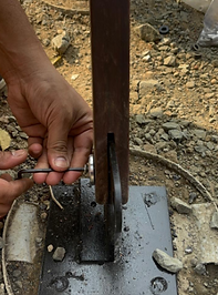
On site, the wooden members were fixed onto steel plates that had been welded to the foundation. Additional metal plates were used to connect corresponding wooden elements, forming three aligned structural frames. Steel cables were then attached to suspend the table, with turnbuckles used to fine-tune wire tension.
The subsequent step involved assembling the components using steel wires. The wooden members were secured to steel plates, which were welded to the foundation and fastened with screws. Corresponding wooden members were then joined together using metal plates, resulting in the creation of three rows of such assemblies. Steel cables were utilized to suspend the table, supported by the wooden members. The tension in the wires was adjusted using turnbuckles anchored to the metal plates embedded in the foundation.
The final phase involved adjusting cable tension, aligning the table top, and ensuring level accuracy. Through careful calibration, the structure achieved both visual lightness and structural stability, bringing the project to completion.


.jpeg)
.jpeg)


.jpg)
.jpg)


